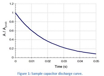
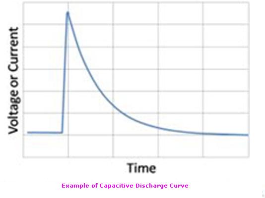
Capacitive discharge resistance welding uses capacitors to store energy for quick release. Figure 1 shows a typical capacitor discharge curve. Capacitive resistance welders, also called capacitive discharge or CD welders, have many advantages over other welder types. Weld nugget formation takes place during the first few milli-seconds of the welding process. A CD welder allows extremely fast energy release with large peak currents. More of the energy goes into weld formation and less into heating surrounding material. The heat affected zone, where the properties of the metal have been changed by rapid heating and cooling, is localized to a small area around the weld spot. The quick discharge rate of CD welders also allows electrically and thermally conductive materials, such as copper or aluminum, to be welded. Capacitive welders deliver repeatable welds even during line voltage fluctuations because weld energy is stored before use.
Spot welding relies on metal resistivity (resistance) to heat and fuse metal. A large current is passed through the work piece metal. Energy is dissipated due to the metal resistance in the form of heat which melts and fuses weld materials. There are two phases to the melting process. The welder must overcome both the material contact resistance and the bulk resistance of the material. Figure 2 shows an example of a micro-scale surface profile. On the micro-scale, material surfaces are rough and only contact in a limited number of locations. In the first few milli-seconds of weld formation the high-resistance metal bridges melt allowing other bridges to come into contact to continue the melting process. When all of the bridges have fused the contact resistance is zero. The bulk resistance of the metal then plays the final role in the weld formation.
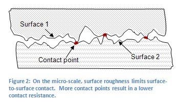
Several other factors play a part in the contact resistance. The larger the contact resistance the hotter the resultant weld. On the micro-scale, contact resistance is reduced when more metal bridges or contact points are formed (see Figure 2). Using more electrode pressure creates more metal bridges. This results in a lower contact resistance and a cooler weld. Conversely, light electrode pressure results in less metal contact, higher resistance, and a hotter weld. An appropriate amount of pressure should be used to insure good weld strength.
Weld Pressure
One way contact resistance can be controlled is through the pressure of the welding electrodes. High electrode pressure reduces contact resistance because the pressure creates more metal bridges or contact points (Figure 2). When contact resistance is reduced, less weld power is consumed at the material interface and therefore the weld is cooler. Conversely, less weld pressure translates to higher contact resistance and a hotter weld. Electrode pressure also contributes to weld strength. The applied pressure forces the liquid metal together during the welding process and allows the metal to mix and solidify. An appropriate amount of pressure should be used to ensure proper weld nugget formation. Table 1 demonstrates how electrode pressure affects weld formation.
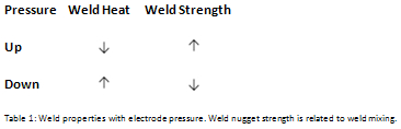
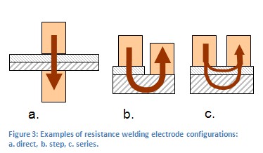
Figure 3 shows several electrode configurations used in resistance welding. Figure 3a is called a direct weld. Current is passed from one electrode, through both work pieces and out an opposing electrode. Figure 3b shows a step electrode configuration. This configuration is used when there is access to only one side of the work piece and an electrode can be placed on both materials. Figure 3c is a series configuration. Electrodes can only be placed on one metal surface from one side. Current is divided between the two parts. This weld configuration requires more weld energy.